Administrating support wizards
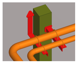
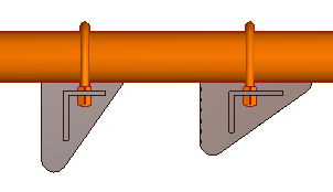
In the Support Designer tool, the easiest way for a designer to add supports into the 3D model is by using a support wizard. Support wizard templates allow the designer to insert support components (=primary supports) and generate the required steel construction (=secondary supports) at the same time, as shown in the picture below. Normal, non-wizard based support templates only generate the secondary supports.
Since support wizard templates implement more automation than normal support templates, also the project administrator has more to do. The project administrator must create the required support wizards for the project, using parametric templates that define the rules (the use cases) that allow the designers to create supports for different pipe sizes. You can find an example of creating a support wizard template in Create the support templates.
Support wizards use by default the same Functional Description for every primary support, but the user can also select primary supports interactively, as needed. The selection can be enabled by activating the 'SelectPrimariesSetup' script, which can be found from the library database of the CADMATIC example project. Additionally, different piping specifications can define a different primary support for the same Functional Description.
Support wizards can be configured to function either so that the program calculates the size of the angle bars and the fastening plates from the nominal size of the supported pipe or so that the designer chooses the components manually.
Before continuing, make sure you are familiar with the Concepts of the Support Designer tool.
Project requirements
To allow support wizards to be used, the project environment must meet the following requirements.
Requirements for Piping
- The direction of the pipes to be supported does not matter as long as all the selected pipes are almost parallel to each other. The tolerances for the slope (3 degrees) and the rotation (0.5 degrees) are fixed in the interface scripts.
- The center points of all primary supports are in the same plane.
- The direction of every primary support is exactly the same or exactly the opposite.
- Every picked piping part must be a straight piece of pipe and must intersect the plane of the primary supports. If any of the pipes fail this test, the whole operation is canceled.
- A primary support with the functional code 'su4' must exist in the piping specification for every picked pipeline in the same specification with the picked pipe. The 'SelectPrimariesSetup' script can be activated to enable selection of other Functional Descriptions, if necessary.
- The elevation of the pipe is only taken from one pipe. The user is responsible for checking that the elevation of pipes fits to the secondary construction. If there are, for example, two pipes with a different elevation, it is of course possible to make a tilted support by defining the direction of primaries accordingly.
Requirements for Primary Supports
-
Geometry type must be DM_GT_TEE (number 7).
-
Geometry point number 3 must define the connection between the primary and secondary support. The location of the surface of the secondary steel is defined according to this point.
-
Geometry point number 3 must point to Z-negative direction from the center point of the primary support (from geometry point number 4).
-
All node points of the primary support are of type Auxiliary point, and the directions of these points must follow the rule for DM_GT_TEE, although they are of type Auxiliary point.
-
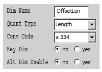
In the Dimension Table of the primary support, it is possible to define the required offset of the secondary steel from the center line of the primary support by using the dimension attribute 'OffsetLen'. Otherwise default values for the offset are used; the default values are defined for the most common nominal sizes, from DN15 to DN500.
Requirements for Secondary Steels
- The secondary steels must use equal or unequal angle profiles.
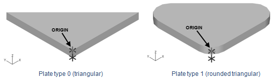
Requirements for Plates
For example, triangular and rounded triangular plates must meet the following requirements:
-
The plate is defined to positive XY-quarter of the XY-plane.
-
The length of the side of the plate must be the first dimension attribute of type 'NS'.
-
The thickness of the plate is defined in the first dimension attribute of type 'Length'.
-
The rounding of the plate (for plate type 1 only) is defined in the second dimension attribute of type 'Length'.
-
The dimension attribute 'PlateType' with the quantity type 'Pieces' must exist. The value of this attribute is 0 for triangular plates and 1 for rounded triangular plates.
Support wizard setup
Before designers can start using support wizards in Plant Modeller, project administrator must create the initial setup, as described below.
Create the support templates
In this example, we create a pipe support wizard template that defines several ranges of nominal sizes, allowing the pipe support wizard to automatically select a suitable angle bar and fastening plate for pipes of different sizes.
Prerequisites
- Library contains the objects to be used for the primary support (for example, U-bolt) and the secondary steel support (equal angle profiles).
Do the following:
-
In Plant Modeller, select File > Environment > All library and project. The Project Environment dialog opens.
-
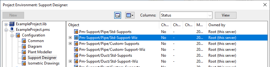
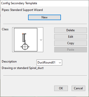
In [project] > Configuration > Support Designer, double-click the Pm-Support/Pipe/Std-Support-Wiz configuration object. The Config Secondary Template dialog opens.
-
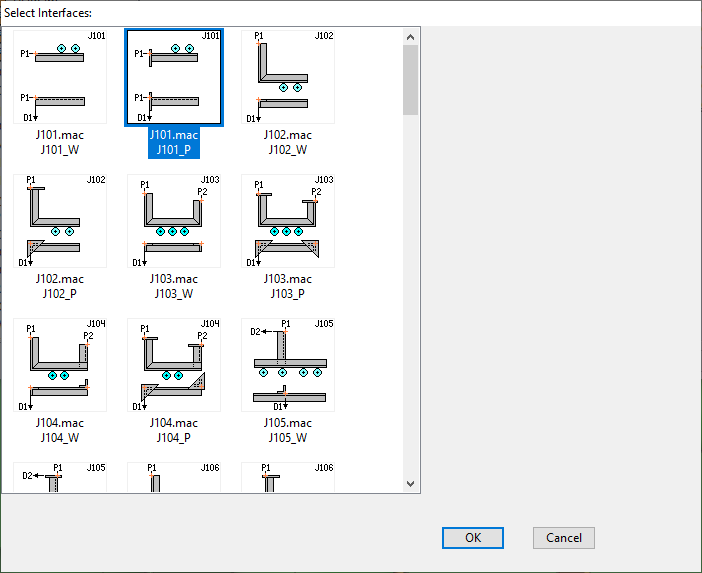
Click New. The Select Interfaces dialog opens, listing the available support interfaces.
-
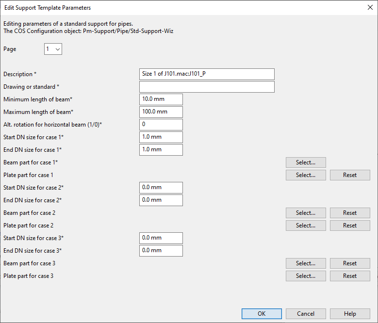
Select the support interface to use and click OK. The Edit Support Template Parameters dialog opens.
-
Define the general parameters:
-
Description – Enter a name for the template.
-
Drawing or standard – Enter the name of the drawing or standard to use for supports created with this template.
-
Minimum length of beam, Maximum length of beam – Specify the minimum and maximum length of beam parts that can be created with this template.
-
Alt. rotation for horizontal beam – If this template uses beams that have unequal legs, this setting specifies on which side of the beam to fasten the primary support:
- 0 – The primary support is fastened to the shorter side of the L-bar.
- 1 – The primary support is fastened to the longer side of the L-bar, except in template types J106 and J107 where the default direction 0 means the longer side.
-
-
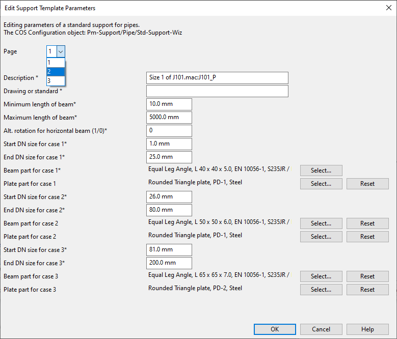
When a support designer uses the support wizard to create a secondary support, the biggest nominal size among the pipes to be supported determines the "case" that the program selects from this support template. Each case defines the beam part and plate part to use for constructing the support. Accordingly, in the template you must define the parameters of each case, that is, of each different type of secondary support that can be created from the template, starting from case 1:
-
Start DN size for case 1, End DN size for case 1 – Define the minimum and maximum nominal sizes that will use these parameters.
-
Beam part for case 1 – Click Select and select the beam profile of this case from the library.
-
Plate part for case 1 – Click Select and select the plate part of this case (plate type 0 or plate type 1) from the library.
-
-
Define each additional case in the same way. If more than three are needed (the maximum is nine cases), select the next parameter page from the Page field.
-
When all the required parameters are defined, click OK.
Create 2D symbols, drawing sheet, and ICGD
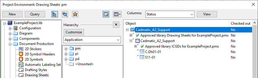
In the Project Environment dialog, in [library] > Document Production, prepare the following and approve them to be used in the project:
- In 2D Symbols, define any symbols that the support wizard is to use.
- In Drawing Sheets, define the drawing sheet the support wizard is to use.
- In ICGDs, define the ICGD that the support wizard is to use.
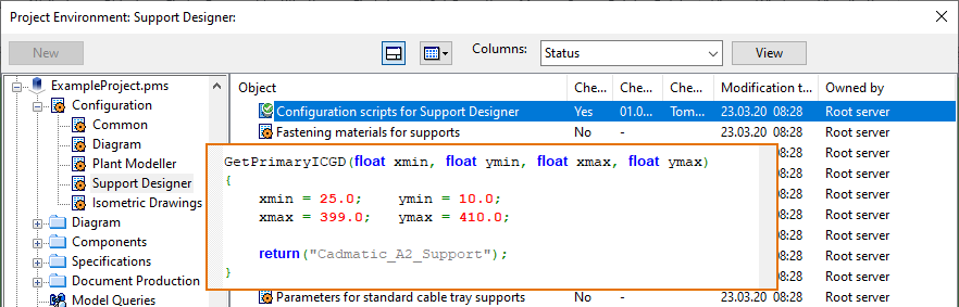
Note that in [project] > Configuration > Support Designer, the Configuration scripts for Support Designer configuration object must contain the name of the drawing sheet (in this example, 'Cadmatic_A2_Support') without the '.ic' drawing sheet extension and assign the values for the drawing area (xmin, xmax and ymin, ymax) defined in the sheet. This area is used for the 'Front' and 'Top' view of the support. Axonometric view, if it exists, is outside this area and its location is defined separately in interactive settings.
Define settings for support spool tool
Define settings for automatic generation of pipe spool support drawings.
Prerequisites
-
In the Project Environment dialog, the Support Spools DW Settings configuration object has been moved from [library] > Resources > User Data to [project] > Resources > User Data.
Do the following:
-
In Plant Modeller, select Documents > Drawings, and then open a support drawing.
-
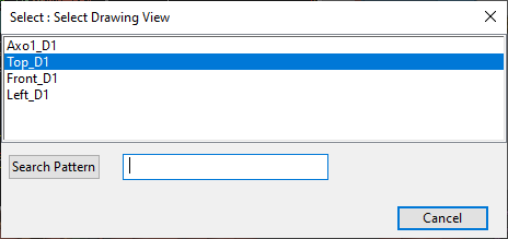
On the Tools tab, select Elo Tools > Support Spools Settings. The Select Drawing View dialog opens.
-
Select the drawing view, for example 'Top_D1'. The Support Spool Tool Settings dialog opens.
-
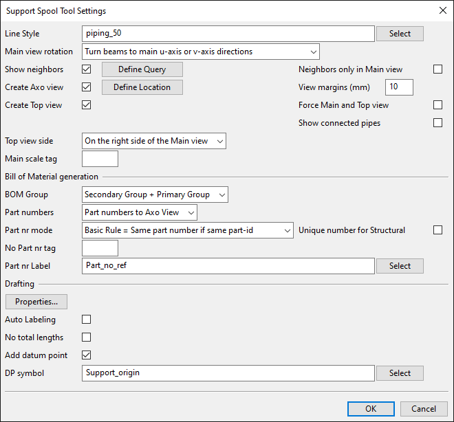
Define the settings.
-
Line Style – Select one of the available Line Attribute Styles from the list.
-
Main view rotation – Select how the program should rotate a support to display it in a drawing view.
-
Show neighbors – If selected, click Define Query to define a query that selects which neighboring objects (such as Hull or building objects) to show in the drawing as a reference.
-
Create Axo view – If selected, click Define Location to select the Axo view position by defining the minimum and maximum values in both horizontal and vertical direction within the sheet area.
-
Create Top view – If selected, use the Top View Side field to select the location of the Top view with respect to the main view in the drawing sheet.
-
BOM Group – Select whether the BOM displayed in the sheet should display only the secondary supports or both primary and secondary supports.
-
Part numbers – Select whether to assign part numbers and show them in Axo view.
-
No Part nr tag – Parts that have the tag defined in this field will not be numbered.
-
Part nr Label – Select the part number label to use in the support drawing.
-
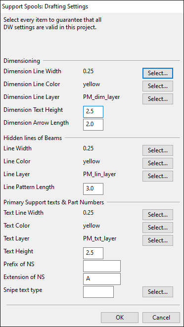
Drafting – Click Properties to define drafting settings for different object types. For example color, line width, layer, text height, arrow length. These settings are valid for this project only.
-
Auto Labeling – If selected, click Define Settings to define settings for automatic labeling.
-
Dimension Style – Select whether to always center dimension or move short dimensions out.
-
No total lengths – If selected, total beam length is not displayed when there are partial lengths.
-
Add datum point – If selected, use the DP symbol field to define which symbol to show as the datum point in support drawings. See also Datum point in support drawings.
-
-
Click OK.
Parameters for cable tray supports and support wizards
In the Project Environment dialog, in [project] > Configuration > Support Designer, interfaces for cable tray supports are defined using the following configuration objects.
-
Pm-Support/CT/Std-Supports, Pm-Support/CT/Custom-Supports – There are no default interfaces for cable tray supports. The project administrator must create the required interfaces.
-
Pm-Support/CT/Std-Support-Wiz, Pm-Support/CT/Custom-Support-Wiz – The delivery environment contains Default interfaces for cable tray support wizards. The project administrator can create additional interfaces.
The project administrator can create new interfaces as described in Adding custom support interfaces to projects.
For more information on interfaces, see Interfaces.
Default interfaces for cable tray support wizards
These are the default interfaces for the support wizards of custom cable tray supports:
| CTray_ceil_01 |

|
||
|---|---|---|---|
| CTray_floor_01 |

|
||
| CTray02 |

|
||
| CTray_AngleBar_P |

|
||
| DC01 |

|
||
| DC02 |

|
||
Parameters for duct supports and support wizards
In the Project Environment dialog, in [project] > Configuration > Support Designer, interfaces for duct supports are defined using the following configuration objects:
- Pm-Support/Duct/Std-Supports, Pm-Support/Duct/Custom-Supports – There are no default interfaces for duct supports. The project administrator must create the required interfaces.
- Pm-Support/Duct/Std-Support-Wiz, Pm-Support/Duct/Custom-Support-Wiz – The delivery environment contains Default interfaces for duct support wizards. The project administrator can create additional interfaces.
The project administrator can create new interfaces as described in Adding custom support interfaces to projects.
For more information on interfaces, see Interfaces.
Default interfaces for duct support wizards
These are the default interfaces for the support wizards of standard and custom duct supports:
| DuctHor01_1 |

|
||
|---|---|---|---|
| DuctHor02_1 |

|
||
| DuctHor03_1 |

|
||
| DuctVer01_1 |

|
||
Parameters for pipe supports and support wizards
In the Project Environment dialog, in [project] > Configuration > Support Designer, interfaces for pipe supports are defined using the following configuration objects:
- Pm-Support/Pipe/Std-Supports, Pm-Support/Pipe/Custom-Supports – The delivery environment contains default interfaces for secondary pipe supports.
- Pm-Support/Pipe/Std-Support-Wiz, Pm-Support/Pipe/Custom-Support-Wiz – The delivery environment contains Default interfaces for pipe support wizards.
The project administrator can create new interfaces as described in Adding custom support interfaces to projects.
For more information on interfaces, see Interfaces.
Default interfaces for pipe support wizards
There are two variants of each pipe support wizard interface—one with plates (suffix:_P) and another without plates (suffix: _W): J101_P and J101_W. The project administrator can use these interfaces for creating support wizard templates that have the parameters the administrator specifies.
- You can select an interface with plates to create a template that does not use plates, but this is not recommended.
- If you select an interface without plates, then the template cannot use plates.
The thumbnail picture of the interface shows which points and directions will be requested from the user and in which order. In many cases, there are two alternative orientations for the angle profiles, and the user must select which one to use. For the types J101–J105 and J108, the location of the primary supports is defined according to P1, but for the types J106 and J107 the user must explicitly pick one point from the plane of primary supports.
These are the default interfaces for the support wizards of pipe supports:
| Plate Types | Alternative Rotation | Sub Types | Parameters | ||||
|---|---|---|---|---|---|---|---|
| A | B | C | D | ||||
| J101_W | - | Yes |

|

|
- | - | - |
| J101_P | 0,1,2,3,4 | Yes |

|

|
- | - | - |
| J102_W | - | Yes |

|

|

|

|
H |
| J102_P | 0,1,2,3,4 | Yes |

|
Same as J102_W |
Same as J102_W |
Same as J102_W |
H |
| J103_W | - | Yes |

|

|
- | - | H1, H2 |
| J103_P | 0,1,2,3,4 | Yes |

|
Same as J103_W |
- | - | H1, H2 |
| J104_W | - | Yes |

|

|

|

|
H1, H2 |
| J104_P | 0,1,2,3,4 | Yes |

|
Same as J104_W |
Same as J104_W |
Same as J104_W |
H1, H2 |
| J105_W | - | Yes |

|

|

|

|
H, B |
| J105_P | 0,1,2,3,4 | Yes |

|
Same as J105_W |
Same as J105_W |
Same as J105_W |
H, B |
| J106_W | - | Yes |

|

|
- | - | H |
| J106_P | 0,1,2,3,4 | Yes |

|
Same as J106_W |
- | - | H |
| J107_W | - | Yes |

|
- | - | - | H1, H2 |
| J107_P | 0,1,2,3,4 | Yes |

|
- | - | - | H1, H2 |
| J108_W | - | Yes |

|

|

|

|
H1, H2 |
| J108_P | 0,1,2,3,4 | Yes |

|
- | - | - | H1, H2 |
| No Sub Types | |||||||
| Turned position |
|||||||
| J109_W | - | Yes |

|

|
|
|
|
| J109_P | 0,1,2,3 | Yes |

|
||||
| J110_W | - | Yes |

|
||||
| J110_P | 0,1,2,3 | Yes |

|
||||
| J111_W | - | Yes |

|
||||
| J111_P | 0,1,2,3 | Yes |

|
||||
| J112_W | - | Yes |

|
||||
| J112_P | 0,1,2,3 | Yes |

|
||||
| J113_W | - | Yes |

|
||||
| J113_P | 0,1,2,3 | Yes |

|
||||
| J114_W | - | Yes |

|
No | |||
| J114_P | 0,1,2,3,4 | Yes |

|
No | |||
| J115_W | - | No |

|
||||
| J115_P | 0,1 | No |

|
||||
| J116_W | - | Yes, horizontal beam only |

|
No | |||
| J116_P | 0,1,2,3,4 | Yes, horizontal beam only |

|
No | |||
| J117_W | - | Yes |

|
No | |||
| J117_P | 0,1,2,3,4 | Yes |

|
No | |||
| J118_W | - | Yes |

|
No | |||
| J119_W | - | Yes |

|
||||
| J119_P | 0,1,2,3,4 | Yes |

|
||||
| J120_W | - | No |

|
No | |||
| J120_P | 0,1,2,3,4 | No |

|
No | |||
| J121_W | - | Yes |

|
||||
| J121_P | 0,1,2,3,4 | Yes |

|
||||
| J121_W |

|
||||||
| J121_P |

|
||||||
| J122_W |

|
||||||
| J122_P |

|
||||||
| J123_W |

|
||||||
| J123_P |

|
||||||
| J124_W |

|
||||||
| J124_P |

|
||||||
| J125_W |

|
||||||
| J125_P |

|
||||||
| J126_W |

|
||||||
| J126_P |

|
||||||
| J127_W |

|
||||||
| J127_P |

|
||||||
| J128_W |

|
||||||
| J128_P |

|
||||||
| DuctRound01_1 | 0,1,2,3,4 | Yes |

|
|
|||
| R101_W |

|
||||||
| MultiClamp |

|
||||||
About the 'Plate Types' Column
In interfaces that use plates, the plate types must be defined exactly as they are defined in the default interfaces of the CADMATIC delivery environment. The plate type defines the plate's shape, origin, rotation, and dimension attributes.
- PlateType = 0, Equal triangle plates, origin in 90 degree corner
- PlateType = 1, Equal rounded triangle plates, origin in 90 degree corner
- PlateType = 2, Circular plates, origin in the center point
- PlateType = 3, Equal or unequal rounded triangle plates, origin in the center point
- PlateType = 4, Equal or unequal rectangle plates, origin in the center point
About the 'Alternative Rotation' Column
In interfaces that use unequal angle bars as secondary supports, 'alternative rotation' refers to the ability of the support designer to select whether the primary support is fastened to the long or the short side of the horizontal angle bar. This setting is defined in the parameters of the support template.
The example below shows the support type J101_P with the primary support fastened to the short side of the angle bar on the left, and to the long side of the angle bar on the right.
About the 'Sub Types' and 'Parameters' Columns
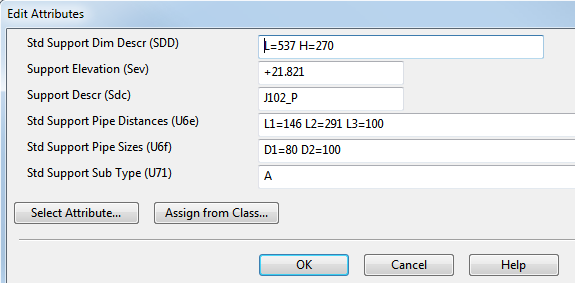
Support Types J101–J108 get a subtype letter and parameters for the measurements. These are given as attributes to the support when the support drawing is created.
The automatically created attributes can be viewed with the Attributes command of the Support Designer tool—see Attributes.
The example below shows attributes for the support type J102_P, subtype A.